
1989
3.
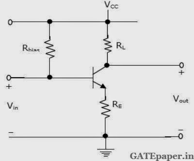
The feedback amplifier shown in
figure has

a.
Current – Series feedback with large
input impedance and large output impedance
b.
Voltage – Series feedback with large
input impedance and low output impedance
c.
Voltage – Shunt feedback with low
input impedance and low output impedance
d.
Current – Shunt feedback with low
input impedance and low output impedance
Answer: C
1993
4.
Negative feedback in amplifiers
a.
improves the signal to noise ratio
at the input
b. improves the signal to noise ratio
at the output
c.
does not affect the signal to noise
ratio at the output
d. reduces distortion
Answer: D
Solution :
https://www.youtube.com/watch?v=vOY2wtpSxkA
1995
2.
To obtain very high input and output
impedance in a feedback amplifier, the topology mostly used is
a.
Voltage Series
b. Current Series
c.
Voltage Shunt
d. Current Shunt
Answer: B
8.
An amplifier has an open loop gain
of 100, and its lower and upper cutoff frequency of 100 Hz and 100 kHz
respectively. A feedback network with a feedback factor of 0.99 is connected to
the amplifier. The new lower and upper cutoff frequencies are at __________ and
________
Answer: 1 Hz and 10 MHz
1996
3.
In the circuit shown, ‘N’ is a
finite gain amplifier with a gain of K, large input impedance and very low
output impedance. The input impedance of the feedback amplifier with the
feedback impedance Z connected as shown will be ______________

Answer: D
1997
1.
In the BJT amplifier shown in
figure, the transistor is based in the forward active region. Putting a
capacitor across RE will
a.
Decrease the voltage gain and
decrease the input impedance
b. Increase the voltage gain and
decrease the input impedance
c.
decrease the voltage gain and
increase the input impedance
d. Increase the voltage gain and
increase the input impedance
Answer: B
Solution : https://www.youtube.com/watch?v=dyVSC2Y1uGI
5.
Negative feedback in
1.
Voltage Series configuration a. Increases
input impedance
2.
Current Shunt configuration b. Decreases
input impedance
c. Increases closed loop gain
d. leads to oscillation
Answer: 1-a, 2-b
Solution:
Solution:
1998
2.
The circuit of the figure is an
example of feedback of the following type

a.
Current Series
b.
Current Shunt
c.
Voltage Series
d.
Voltage Shunt
Answer: D
7.
In a Shunt – Shunt negative feedback
amplifier, as compared to the basic amplifier
a.
Both, input and output impedances
decreases
b. Input impedance decreases and output
impedance increases
c.
Input impedance increases and output
impedance decreases
d. Both, input and output impedances
increases
Answer: A
1999
2.
Negative feedback in an amplifier
a.
Reduces gain
b. Increases frequency and phase
distortions
c.
Reduces bandwidth
d. Increases noise
Answer: C
5.
An amplifier has an Open loop gain
of 100, an input impedance of 1 kΩ and an output impedance of 100 Ω.
A feedback network with a feedback factor of 0.99 is connected to the amplifier
in a voltage series feedback mode. The new input and output impedances,
respectively are
a.
10 Ω and 1 Ω
b. 10 Ω and 10 kΩ
c.
100 kΩ and 1 Ω
d. 100 kΩ and 1 kΩ
Answer: C
2000
33. For a feedback amplifier, the open
loop transfer function has three poles at 100 k rad/sec, 1 M rad/sec and 10 M
rad/sec. The low frequency open loop gain is 1000 and the feedback factor (β)
is 1. Use Bode plots to determine the phase margin of the amplifier. Is the
amplifier stable?
Answer: Amplifier is Unstable.
2002
1.
In a negative feedback amplifier
using voltage-series (Voltage sampling and series mixing) feedback,
a.
Ri decreases and Ro
decreases
b. Ri decreases and Ro
increases
c.
Ri increases and Ro
decreases
d. Ri increases and Ro
increases
Answer: C
2003
6.
An amplifier without feedback has a
voltage gain of 50, input resistance of 1 KΩ
and output resistance of 2.5 KΩ. The input resistance of the current-shunt
negative feedback amplifier using the above amplifier with a feedback factor of
0.2 is
a.
1/11 KΩ
b. 1/5 KΩ
c.
5 KΩ
d. 11 KΩ
Answer: A
2004
2.
Voltage series feedback (also called
series-shunt feedback) results in
a.
Increase in both input and output
impedances
b. Decrease in both input and output
impedances
c.
Increase in input impedance and
decrease in output impedance
d. Decrease in input impedance and
increase in output impedance
Answer: C
2005
1.
The effect of current shunt feedback
in an amplifier is to
a.
Increase the input resistance and
decrease the output resistance.
b. Increase both input and output
resistances
c.
Decrease both input and output
resistances
d. Decreases the input resistance and
increase the output resistance
Answer: D
2006
1.
The input impedance(Zi)
and output impedance (Zo) of an ideal Transconductance (voltage
controlled current source) amplifier are
a.
Zi = 0, Zo = 0
b. Zi = 0, Zo = ∞
c.
Zi = ∞,
Zo = 0
d. Zi = ∞,
Zo = ∞
Answer: D
2007
1.
In a Transconductance amplifier, it
is desirable to have
a.
A large input resistance and a large
output resistance
b. A large input resistance and a small
output resistance
c.
A small input resistance and a large
output resistance
d. A small input resistance and a small
output resistance
Answer: A
2010
1.
The amplifier circuit shown below
uses a silicon transistor. The capacitors CC and CE can
be assumed to be short at signal frequency and effect of output resistance ro
can be ignored. If CE is disconnected from the circuit, which one of
the following statements is TRUE.

a.
The input resistance Ri
increases and magnitude of voltage gain AV decreases
b.
The input resistance Ri
decreases and magnitude of voltage gain AV increases
c.
The input resistance Ri
decreases and magnitude of voltage gain AV decreases
d.
The input resistance Ri
increases and magnitude of voltage gain AV increases
Answer: A
2013
2.
In a voltage – voltage feedback as
shown below, which one of the following statements is TRUE, if the gain K is
increased?

a.
The input impedance increases and
output impedance decreases
b. The input impedance increases and
output impedance increases
c.
The input impedance decreases and
output impedance decreases
d. The input impedance decreases and
output impedance increases
Answer: A
2014
2.
A good current buffer has
a.
Low input impedance and low output
impedance
b. Low input impedance and high output
impedance
c.
high input impedance and low output
impedance
d. high input impedance and high output
impedance
Answer: B
Solution : https://www.youtube.com/watch?v=vdYmByP9zYY
3.
In the ac equivalent circuit shown
in the figure, if iin is the input current and RF is very
large, then the type of feedback is

a.
Voltage – Voltage feedback
b. Voltage – Current feedback
c.
Current – Voltage feedback
d. Current – Current feedback
Answer: B
Solution : https://www.youtube.com/watch?v=otvYW4oudRg
2.
The feedback topology in the
amplifier circuit (the base bias circuit is not shown for simplicity) in the
figure is

a.
Voltage – Shunt feedback
b. Current – Series feedback
c.
Current – Shunt feedback
d. Voltage – Series feedback
Answer: B
Solution : https://www.youtube.com/watch?v=MNduRhMC6zk
2.
The desirable characteristics of a
Transconductance amplifier are
a.
High input resistance and High
output resistance
b. High input resistance and Low output
resistance
c.
Low input resistance and High output
resistance
d. Low input resistance and Low output
resistance
Answer: A
Solution : https://www.youtube.com/watch?v=1RsZ43lyRhs
1.
If the emitter resistance in a
common emitter voltage amplifier is not bypassed, it will
a.
Reduce both the voltage gain and the
input impedance
b. Reduce the voltage gain and increase
the input impedance
c.
Increase the voltage gain and reduce
the input impedance
d. Increase both the voltage gain and
the input impedance
Answer: B
Solution : https://www.youtube.com/watch?v=4YjclPDw5lM
2015
1. Negative
feedback in a closed loop control system DOES NOT
a. Reduce
the overall gain
b. Reduce
bandwidth
c. Improve
disturbance rejection
d. Reduce
sensitivity to parameter variation
Answer: B
Solution: https://www.youtube.com/watch?v=TFCXqD_Tu4s
No comments:
Post a Comment