Network Synthesis & Driving Point Impedance - Topicwise GATE Questions on Network Theory (from 2003)

2005
1. The first and Last critical frequency of an RC driving point impedance function must respectively be
a) a zero and a pole
b) a zero and a zero
c) a pole and a pole
d) a pole and a zero

Answer:D
Solution : https://www.youtube.com/watch?v=noq2x3cDycY


2006
2. The first and the last critical frequencies (singularities) of a driving point impedance function of a passive network having two kinds of elements, are a pole and a zero respectively. The above property will be satisfied by
a) RL network only
b) RC network only
c) LC network only
d) RC as well as RL networks

Answer:B
Solution : https://www.youtube.com/watch?v=L4AUTybSCjk

3. A negative resistance Rneg is connected to a passive network N having driving point impedance Z1(s) as shown below. For Z2(s) to be positive real,

Answer:A
Solution : https://www.youtube.com/watch?v=ESM5mIZBEeU


2008
4. The driving point impedance of the following network is given as shown. The component values are

Answer:D
Solution : https://www.youtube.com/watch?v=CI2Na_stYRg

Steady State Analysis of AC and DC circuits - Topicwise GATE Questions on Network Theory (from 2003)

2005
1. For the circuit in figure, the instantaneous current i1(t) is

Answer:A
Solution : https://www.youtube.com/watch?v=BcmlFVwT5C4


2007
2. In the AC network shown in the figure, the phasor voltage VAB(in volts) is:

Answer:D
Solution : https://www.youtube.com/watch?v=CNz1YebFlDw


2008
Common Data Questions: 3 & 4
The following series RLC circuit with zero initial conditions is excited by a unit impulse function δ(t).

3. For t > 0, the output voltage Vc(t) is

Answer:D
Solution : https://www.youtube.com/watch?v=DB4jmdoaFIk

4. For t > 0, the voltage across the resistor is

Answer:B
Solution (3 & 4) : https://www.youtube.com/watch?v=nn6PggFjKgA

2009
5. The time domain behaviour of an RL circuit is represented as shown below. For an initial current of i(0) = Vo/R, the steady state value of the current is given by

Answer:A
Solution : https://www.youtube.com/watch?v=VBFOXuUEuKE


2010
6. The current I in the circuit shown is

a) - j1 A
b) j1 A
c) 0 A
d) 20 A
Answer:A
Solution : https://www.youtube.com/watch?v=dKZILrD0vOM

2011
7. In the circuit shown below, the Norton equivalent current in amperes with respect to the terminals P and Q is

a) 6.4 - j 4.8
b) 6.56 - j 7.87
c) 10 + j 0
d) 16 + j 0


Answer:A
Solution : https://www.youtube.com/watch?v=HsLyDiBmxx4

8. The circuit shown below is driven by a sinusoidal input Vi = Vpcos(t/RC). The steady state output Vo is

Answer:A
Solution : https://www.youtube.com/watch?v=51KGart3zsQ

9. In the circuit shown below, the current I is equal to

Answer:B
Solution : https://www.youtube.com/watch?v=t9esPoyU5tY

2012
10. In the circuit shown below, the current through the inductor is

Answer:C
Solution : https://www.youtube.com/watch?v=bD4nQW3U4SA

2014
11. In the circuit shown in the figure, the value of node voltage V2 (in volts) is

a) 22 + j 2
b) 2 + j 22
c) 22 – j 2
d) 2 – j 22
Answer:D
Solution : https://www.youtube.com/watch?v=L9li2Lu26iU

12. The steady state output of the circuit shown in the figure is given by y(t) = A(ω) sin(ωt + φ(ω)).

If the amplitude |A(ω)| = 0.25, then the frequency ω is
Answer:B
Solution : https://www.youtube.com/watch?v=IIlI8e2TeDg


13. In the circuit shown in the figure,

the value of Vo(t) (in volts) for t → ∞ is ___________
Answer:31.25
Solution : https://www.youtube.com/watch?v=SHT_OgLFZmE

2015
14. In the circuit shown, assume that diodes D1 and D2 are ideal. In the steady state condition, the average voltage Vab (in volts) across 0.5 µF capacitor is ____________

Answer:100
Solution : https://www.youtube.com/watch?v=2ZfO7mplk4g

Resonance (Series and Parallel) - Topicwise GATE Questions on Network Theory (from 2003)

2003
1. A series RLC circuit has a resonance frequency of 1 kHz and a quality factor Q = 100. If each R, L and C is doubled from its original value, the new Q-factor of the circuit is
a) 25
b) 50
c) 100
d) 200

Answer:B
Solution : https://www.youtube.com/watch?v=DCfbRcxcOEM


2004
2. Consider the following statements S1 and S2
S1: at the resonant frequency, the impedance of a series RLC circuit is zero.
S2: In a parallel G-L-C circuit, increasing the conductance G results in increase in its Q-factor.
Which one of the following is correct?
a) S1 is FALSE and S2 is TRUE
b) Both S1 and S2 are TRUE
c) S1 is TRUE and S2 is FALSE
d) Both S1 and S2 are FALSE

Answer:D
Solution : https://www.youtube.com/watch?v=s3hM-idhg2s

2005
3. The condition on R, L and C such that the step response y(t) in figure has no oscillations, is

Answer:C
Solution : https://www.youtube.com/watch?v=JfYzFU9Oc-0

4. In a series RLC circuit, R = 2 kΩ, L = 1 H, and C = 1/400 µF. The resonant frequency is
a) 2 x 10⁴ Hz
b) (1/π) x 104 Hz
c) 104 Hz
d) 2π x 104 Hz

Answer:B
Solution : https://www.youtube.com/watch?v=B9Uk_uA0JbA

2007
5. Two series resonant filters are as shown in the figure. Let the 3-dB bandwidth of filter 1 is B1 and that of Filter 2 is B2. The value of B1/B2 is

a) 4
b) 1
c) 1/2
d) 1/4

Answer:D
Solution : https://www.youtube.com/watch?v=lMKem0ESd64

2010
6. For parallel RLC circuit, which one of the following statements is NOT correct?
a) The bandwidth of the circuit decreases if R is increased
b) The bandwidth of the circuit remains same if L is increased
c) At resonance, input impedance is a real quantity
d) At resonance, the magnitude of input impedance attains its minimum value.

Answer:D
Solution : https://www.youtube.com/watch?v=wPSqMuj0YhY

2013
7. Two magnetically uncoupled inductive coils have Q factors q1 and q2 at the chosen operating frequency. Their respective resistances are R1 and R2. When connected in series, their effective Q factor at the same operating frequency is
a) q1 + q2
b) (1/q1) + (1/q2)
c) (q1R1 + q2R2) / (R1 + R2)
d) (q1R2 + q2R1) / (R1 + R2)
Answer:C
Solution : https://www.youtube.com/watch?v=v7q3ssCyLqw

2014
8. In the circuit shown in the figure, the value of capacitor C (in mF) needed to have critically damped response i(t) is ____________________

Answer:10
Solution : https://www.youtube.com/watch?v=MTY9pmGILi4


9. A series LCR circuit is operated at a frequency different from its resonant frequency. The operating frequency is such that the current leads the supply voltage. The magnitude of current is half the value at resonance. If the values of L, C and R are 1H, 1F and 1Ω respectively, then the operating angular frequency (in rad/sec) is ____________________

Answer:0.46
Solution : https://www.youtube.com/watch?v=qJluHG5_mmk

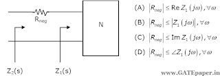
10. In the circuit shown in the figure, the angular frequency ω (in rad/sec), at which the Norton equivalent impedance as seen from terminals b – b' is purely resistive, is _____________

Answer:2
Solution : https://www.youtube.com/watch?v=doL-VE7tziY

2015
11. In the circuit shown, at resonance, the amplitude of the sinusoidal voltage (in volts) across the capacitor is ____________________

Answer:25
Solution : https://www.youtube.com/watch?v=YZq-lDiqadg
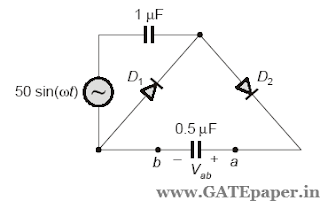
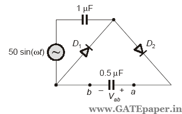
12. The voltage (Vc) across the capacitor (in volts) in the network shown is ______________

Answer:100
Solution : https://www.youtube.com/watch?v=BiEeuX6a218

13. An LC tank circuit consists of an ideal capacitor C connected in parallel with a coil of inductance L having an internal resistance R. The resonant frequency of the tank circuit is

Answer:B
Solution : https://www.youtube.com/watch?v=Y331K9dgrPs

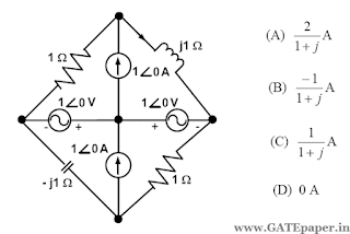
14. In the circuit shown, the current I flowing through the 50 Ω resistor will be zero, if the value of the capacitor C (in µF) is __________________

Answer:20
Solution : https://www.youtube.com/watch?v=ZSJIgQWJiKU

Network Topology and Mutual Inductance - Topicwise GATE Questions on Network Theory (from 2003)

2003
1. The current flowing through the resistance R in the circuit shown has the form Pcos4t, where p is

a) (0.18 + j0.72)
b) (0.46 + j1.90)
c) - (0.18 + j1.90)
d) - (0.192 + j0.144)

Answer: Data is insufficient as inductor values are not given in the figure.


2004
2. Consider the network graph shown in figure. Which one of the following is NOT a ‘tree’ of this group?

Answer:B
Solution : https://www.youtube.com/watch?v=xjHxZjJq8PI

3. The equivalent inductance measured between the terminals 1 and 2 for the circuit shown in figure, is

a) L1 + L2 + M
b) L1 + L2 - M
c) L1 + L2 + 2M
d) L1 + L2 - 2M

Answer:D
Solution : https://www.youtube.com/watch?v=LwuHSGj_pqI

2005
4. Impedance Z as shown in figure is

a) j29 Ω
b) j9 Ω
c) j19 Ω
d) j39 Ω

Answer:B
Solution : https://www.youtube.com/watch?v=tPOeNM7EELI

2008
5. In the following graph, the number of trees (P) and the number of cut-sets (Q) are

a) P = 2, Q = 2
b) P = 2, Q = 6
c) P = 4, Q = 6
d) P = 4, Q = 10
Answer:C

2013
6. The following arrangement consists of an ideal transformer and an attenuator which attenuates by a factor of 0.8. An ac voltage VWX1 = 100 volts is applied across WX to get an open circuit voltage VYZ1 across YZ. Next, an ac voltage VYZ2 = 100 volts is applied across YZ to get an open circuit voltage VWX2 across WX. Then VYZ1/VWX1, VWX2/VYZ2 are respectively

Answer:B
Solution : https://www.youtube.com/watch?v=IJX4fwiz-Fo

2014
7. In the magnetically coupled circuit shown in the figure, 56% of the total flux emanating from one coil links the other coil.

The value of the mutual inductance (in H) is _________________
Answer:2.5
Solution : https://www.youtube.com/watch?v=y2udU1LL1As

Two-Port Networks - Topicwise GATE Questions on Network Theory (from 2003)

2003
1. The impedance parameters Z11 and Z12 of the two port network in figure are

Answer:A
Solution : https://www.youtube.com/watch?v=v16OcXXl_8E

2004
2. For the lattice circuit shown in figure, Za = j2Ω and Zb = 2Ω. The values of the open circuit impedance parameters (Z-parameters) are

Answer:D
Solution : https://www.youtube.com/watch?v=Vn-O5Ll3CwU

2005
3. The ABCD parameters of an ideal n:1 transformer shown in figure are given below. The value of 'x' will be

a) n
b) 1/n
c) n2
d) 1/n2
Answer:B
Solution : https://www.youtube.com/watch?v=wjvAb6BEi9o


4. The h-parameters of the circuit shown in figure are

Answer:D
Solution : https://www.youtube.com/watch?v=lI92Vfd0F1o


2006
5. A two port network is represented by ABCD parameters as shown below. If port-2 is terminated by RL, the input impedance seen at port-1 is given by

Answer:D
Solution : https://www.youtube.com/watch?v=-emJQU9Qsx8

6. In the two port network shown in the figure below, Z12 and Z21 are respectively

Answer:B
Solution : https://www.youtube.com/watch?v=JFOPiiE7frs

2008
Statement for Linked Answer Questions: 7 & 8
A two port network shown below is excited by external DC sources. The voltages and the currents are measured with voltmeters V1, V2 and ammeters A1, A2 (all assumed to be ideal), as indicated. Under following switch conditions, the readings obtained are:

7. The Z-parameter matrix for this network is

Answer:C

8. The h-parameter network for this network is

Answer:A
Solution (7 & 8): https://www.youtube.com/watch?v=_-paorTBZZg


2010
9. For the two-port network shown below, the short-circuit admittance parameter matrix is

Answer:A
Solution : https://www.youtube.com/watch?v=IGYPN1wEH2I

2011
10. In the circuit shown below, the network N is described by the following Y matrix: The voltage gain V2/V1 is

a) 1/90
b) - 1/90
c) - 1/99
d) - 1/11
Answer:D
Solution : https://www.youtube.com/watch?v=nyPW45iQq2c


2012
Common Data for Questions 11 and 12:
With 10 volts DC connected at port A in the linear nonreciprocal two-port network shown below,

the following were observed:
(i) 1Ω connected at port B draws a current of 3 amps
(ii) 2.5Ω connected at port B draws a current of 2 amps
11. With 10 volts DC connected at port A, the current drawn by 7Ω connected at port B is
a) 3/7 A
b) 5/7 A
c) 1 A
d) 9/7 A
Answer:C

12. For the same network, with 6 volts DC connected at port A, 1Ω connected at port B draws 7/3 amp. If 8 volts DC is connected to port A, the open circuit voltage at port B is
a) 6 V
b) 7 V
c) 8 V
d) 9 V
Answer:C
Solution (11 & 12): https://www.youtube.com/watch?v=ghASFX3RYBA

2014
13. In the h – parameter model of 2 – port network given in the figure shown,

the value of h22 (in siemens) is _____________
Answer:1.25
Solution : https://www.youtube.com/watch?v=3xxsvowoMWc

14. For the two – port network shown in the figure,
the impedance (Z) matrix (in Ω) is

Answer:C
Solution : https://www.youtube.com/watch?v=eGw_ZeJwOec

2015
15. The 2 – port Admittance matrix of the circuit shown is given by____________

Answer:A
Solution : https://www.youtube.com/watch?v=jQZIEyucrjU

16. The ABCD parameters of the following 2 – port network are

Answer:B
Solution : https://www.youtube.com/watch?v=iIjMzXmILXk

Transient Analysis of AC and DC circuits - Topicwise GATE Questions on Network Theory (from 2003)

2003
Common circuit for Questions 1 & 2:
Assume that the switch S is in position 1 for a long time and thrown to position 2 at t=0.

1. At t = 0+, the current i1 is
a) – V/2R
b) – V/R
c) – V/4R
d) Zero

Answer:A

 2. I1(s) and I2(s) are the Laplace Transforms of i1(t) and i2(t) respectively. The equations for the loop currents I1(s) and I2(s) for the same circuit shown, after the switch is brought from position 1 to position 2 at t = 0, are

Answer:D
Solution (1 & 2): https://www.youtube.com/watch?v=IiAPEkdgqQQ

2008
3. In the following cirucit, the switch S is closed at t = 0. The rate of change of current di(0+)/dt is given by

Answer:B
Solution : https://www.youtube.com/watch?v=WiYzbTZyhi0


2009
4. The switch in the circuit shown was on position 'a' for a long time, and is moved to position 'b' at time t=0. The current i(t) for t > 0 is given by

Answer:B
Solution : https://www.youtube.com/watch?v=ptI9Yzy17OQ


2010
5. In the cirucit shown, the switch S is open for a long time and is closed at t = 0. The current i(t) for t ≥ 0+ is

Answer:A
Solution : https://www.youtube.com/watch?v=1oztLmwhBL0

2011
6. In the circuit shown below, the initial charge on the capacitor is 2.5 mC, with the voltage polarity as indicated. The switch is closed at time t = 0. The current i(t) at a time t after the switch is closed is

Answer:A
Solution : https://www.youtube.com/watch?v=hQdNpuDt3zU

2014
7. In the figure shown, the ideal switch has been open for a long time.

If it is closed at t = 0, then the magnitude of the current (in mA) through the 4 kΩ resistor at t = 0+ is ____________

Answer:1.25
Solution : https://www.youtube.com/watch?v=lr0Teo6g4nA


2015
8. In the circuit shown, the switch SW is thrown from position A to position B at time t=0. The energy (in µJ) taken from the 3 volts source to charge the 0.1 µF capacitor from 0 volts to 3 volts is

a) 0.3
b) 0.45
c) 0.9
d) 3
Answer:C
Solution : https://www.youtube.com/watch?v=ZbFt7Lkclp8

9. In the circuit shown, switch SW is closed at t =0. Assuming zero initial conditions, the value of Vc(t) (in volts) at t = 1 sec is __________________

Answer:2.528
Solution : https://www.youtube.com/watch?v=_hcH81bC-cg

Post Your Feedback (or) Doubts here.......

Name

Email *

Message *