2015
1.
In the network shown in the figure, all resistors are identical with
R = 300 Ω.
The resistance Rab
(in Ω) of the network is __________________
2.
In the circuit shown, at resonance, the amplitude of the sinusoidal
voltage (in volts) across the capacitor is ____________________
3.
In the circuit shown, the switch SW is thrown from position A to
position B at time t=0. The energy (in µJ) taken from the 3 volts
source to charge the 0.1 µF capacitor from 0 volts to 3 volts is
a)
0.3
b)
0.45
c)
0.9
d)
3
4.
In the given circuit, the values of V1
and V2
(in volts) respectively are
a)
5, 25
b)
10, 30
c)
15, 35
d)
0, 20
5.
In the circuit shown, switch SW is closed at t =0. Assuming zero
initial conditions, the value of Vc(t)
(in volts) at t = 1 sec is __________________
6.
In the given circuit, the maximum power (in Watts) that can be
transferred to the load RL
is _______
7.
In the circuit shown, the average value of the voltage Vab
(in volts) in steady state condition is _________
8.
The 2 – port Admittance matrix of the circuit shown is given
by____________
9.
The voltage (Vc)
across the capacitor (in volts) in the network shown is
______________
10.
An LC tank circuit consists of an ideal capacitor C connected in
parallel with a coil of inductance L having an internal resistance R.
The resonant frequency of the tank circuit is
11.
In the circuit shown, the initial voltages across the capacitors C1
and C2 are 1 volt and 3 volts respectively. The switch is
closed at time t = 0. The total energy dissipated (in Joules) in the
resistor R until steady state is reached, is _______________
12.
In the circuit shown, the Norton equivalent resistance (in Ω)
across terminals a and b is ________
13.
At High frequencies, the peak output voltage Vo (in
volts) is __________
14.
For the current shown in the figure, the Thevenin equivalent voltage
(in volts) across terminals a and b is _______________
15.
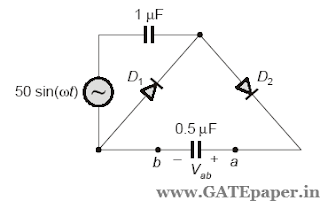
In the circuit shown, assume that diodes D1 and D2
are ideal. In the steady state condition, the average voltage Vab
(in volts) across 0.5 µF
capacitor is ____________
16.
In the circuit shown, the voltage Vx
(in volts) is __________
17.
In the circuit shown, assume that the diodes D1
and D2
are ideal. The average voltage Vab
(in volts) across terminals a and b is _____________
18.
In the circuit shown, the current I flowing through the 50 Ω
resistor
will be zero, if the value of the capacitor C (in µF)
is __________________
19.
The ABCD parameters of the following 2 – port network are


No comments:
Post a Comment