2003
1. The minimum number of equations required to analyze the circuit shown in figure is
a) 3
b) 4
c) 6
d) 7
Solution: https://www.youtube.com/watch?v=_E2r6haGMdw
2. A source of angular frequency 1 rad/sec has source impedance consisting of 1 Ω resistance in series with 1 H inductance. The load that will obtain the maximum power transfer is
a) 1 Ω resistance
b) 1 Ω resistance in parallel with 1 H inductance
c) 1 Ω resistance in series with 1 F capacitor
d) 1 Ω resistance in parallel with 1 F capacitor
Solution: https://www.youtube.com/watch?v=UH5csZbXYgc
3. A series RLC circuit has a resonance frequency of 1 kHz and a quality factor Q = 100. If each R, L and C is doubled from its original value, the new Q-factor of the circuit is
a) 25
b) 50
c) 100
d) 200
Solution: https://www.youtube.com/watch?v=DCfbRcxcOEM
4. The differential equation for the current i(t) in the circuit shown is
Solution: https://www.youtube.com/watch?v=o3XhO6h9PhQ
5. Twelve 1Ω resistances are used to form a cube. The resistance between two diagonally opposite corners of the cube is
a) 5/6 Ω
b) 1/6 Ω
c) 6/5 Ω
d) 3/2 Ω
Solution: https://www.youtube.com/watch?v=DRvJzaE6cqM
6. The current flowing through the resistance R in the circuit shown has the form Pcos4t, where p is
a) (0.18 + j0.72)
b) (0.46 + j1.90)
c) - (0.18 + j1.90)
d) - (0.192 + j0.144)
Answer: Data is insufficient as inductor values are not given in the figure.
Common circuit for Questions 7 & 8:
Assume that the switch S is in position 1 for a long time and thrown to position 2 at t=0.
7. At t = 0+, the current i1 is
a) – V/2R
b) – V/R
c) – V/4R
d) Zero
8. I1(s) and I2(s) are the Laplace Transforms of i1(t) and i2(t) respectively. The equations for the loop currents I1(s) and I2(s) for the same circuit shown, after the switch is brought from position 1 to position 2 at t = 0, are
Solution (7 & 8): https://www.youtube.com/watch?v=IiAPEkdgqQQ
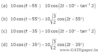
9. An input voltage v(t) = 10√2 cos(t+10o)+ 10√3 cos(2t+10o) volts is applied to a series combination of resistance R = 1Ω and an inductance L = 1H. The resulting steady state current i(t) in amperes is
Solution: https://www.youtube.com/watch?v=n5soJALqqaw
10. The impedance parameters Z11 and Z12 of the two port network in figure are
Solution: https://www.youtube.com/watch?v=v16OcXXl_8E
1. The minimum number of equations required to analyze the circuit shown in figure is
a) 3
b) 4
c) 6
d) 7
2. A source of angular frequency 1 rad/sec has source impedance consisting of 1 Ω resistance in series with 1 H inductance. The load that will obtain the maximum power transfer is
a) 1 Ω resistance
b) 1 Ω resistance in parallel with 1 H inductance
c) 1 Ω resistance in series with 1 F capacitor
d) 1 Ω resistance in parallel with 1 F capacitor
3. A series RLC circuit has a resonance frequency of 1 kHz and a quality factor Q = 100. If each R, L and C is doubled from its original value, the new Q-factor of the circuit is
a) 25
b) 50
c) 100
d) 200
4. The differential equation for the current i(t) in the circuit shown is
5. Twelve 1Ω resistances are used to form a cube. The resistance between two diagonally opposite corners of the cube is
a) 5/6 Ω
b) 1/6 Ω
c) 6/5 Ω
d) 3/2 Ω
6. The current flowing through the resistance R in the circuit shown has the form Pcos4t, where p is
a) (0.18 + j0.72)
b) (0.46 + j1.90)
c) - (0.18 + j1.90)
d) - (0.192 + j0.144)
Answer: Data is insufficient as inductor values are not given in the figure.
Common circuit for Questions 7 & 8:
Assume that the switch S is in position 1 for a long time and thrown to position 2 at t=0.
7. At t = 0+, the current i1 is
a) – V/2R
b) – V/R
c) – V/4R
d) Zero
8. I1(s) and I2(s) are the Laplace Transforms of i1(t) and i2(t) respectively. The equations for the loop currents I1(s) and I2(s) for the same circuit shown, after the switch is brought from position 1 to position 2 at t = 0, are
9. An input voltage v(t) = 10√2 cos(t+10o)+ 10√3 cos(2t+10o) volts is applied to a series combination of resistance R = 1Ω and an inductance L = 1H. The resulting steady state current i(t) in amperes is
10. The impedance parameters Z11 and Z12 of the two port network in figure are


No comments:
Post a Comment