2006
1. A two port network is represented by ABCD parameters as shown below. If port-2 is terminated by RL, the input impedance seen at port-1 is given by
Solution: https://www.youtube.com/watch?v=-emJQU9Qsx8
2. In the two port network shown in the figure below, Z12 and Z21 are respectively
Solution: https://www.youtube.com/watch?v=JFOPiiE7frs
3. The first and the last critical frequencies (singularities) of a driving point impedance function of a passive network having two kinds of elements, are a pole and a zero respectively. The above property will be satisfied by
a) RL network only
b) RC network only
c) LC network only
d) RC as well as RL networks
Solution: https://www.youtube.com/watch?v=L4AUTybSCjk
4. A 2 mH inductor with some initial current can be represented as shown below, where 's' is the Laplace Transform variable. The value of initial current is :
a) 0.5 A
b) 2.0 A
c) 1.0 A
d) 0.0 A
Solution: https://www.youtube.com/watch?v=145BHvtN10o
5. In the figure shown below, assume that all the capacitors are initally uncharged. If Vi(t) = 10 u(t) volts, then Vo(t) is given by
Solution: https://www.youtube.com/watch?v=oA-NdSmNq1c
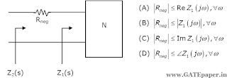
6. A negative resistance Rneg is connected to a passive network N having driving point impedance Z1(s) as shown below. For Z2(s) to be positive real,
Solution: https://www.youtube.com/watch?v=ESM5mIZBEeU
1. A two port network is represented by ABCD parameters as shown below. If port-2 is terminated by RL, the input impedance seen at port-1 is given by
2. In the two port network shown in the figure below, Z12 and Z21 are respectively
3. The first and the last critical frequencies (singularities) of a driving point impedance function of a passive network having two kinds of elements, are a pole and a zero respectively. The above property will be satisfied by
a) RL network only
b) RC network only
c) LC network only
d) RC as well as RL networks
4. A 2 mH inductor with some initial current can be represented as shown below, where 's' is the Laplace Transform variable. The value of initial current is :
a) 0.5 A
b) 2.0 A
c) 1.0 A
d) 0.0 A
5. In the figure shown below, assume that all the capacitors are initally uncharged. If Vi(t) = 10 u(t) volts, then Vo(t) is given by
6. A negative resistance Rneg is connected to a passive network N having driving point impedance Z1(s) as shown below. For Z2(s) to be positive real,


No comments:
Post a Comment