
2005
1. For the circuit in figure, the instantaneous current i1(t) is

Solution : https://www.youtube.com/watch?v=BcmlFVwT5C4
2007
2. In the AC network shown in the figure, the phasor voltage VAB(in volts) is:

Solution : https://www.youtube.com/watch?v=CNz1YebFlDw
2008
Common Data Questions: 3 & 4
The following series RLC circuit with zero initial conditions is excited by a unit impulse function δ(t).

3. For t > 0, the output voltage Vc(t) is

Solution : https://www.youtube.com/watch?v=DB4jmdoaFIk
4. For t > 0, the voltage across the resistor is

Solution (3 & 4) : https://www.youtube.com/watch?v=nn6PggFjKgA
2009
5. The time domain behaviour of an RL circuit is represented as shown below. For an initial current of i(0) = Vo/R, the steady state value of the current is given by

Solution : https://www.youtube.com/watch?v=VBFOXuUEuKE
2010
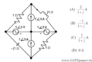
6. The current I in the circuit shown is

a) - j1 A
b) j1 A
c) 0 A
d) 20 A
Solution : https://www.youtube.com/watch?v=dKZILrD0vOM
2011
7. In the circuit shown below, the Norton equivalent current in amperes with respect to the terminals P and Q is

a) 6.4 - j 4.8
b) 6.56 - j 7.87
c) 10 + j 0
d) 16 + j 0
Solution : https://www.youtube.com/watch?v=HsLyDiBmxx4
8. The circuit shown below is driven by a sinusoidal input Vi = Vpcos(t/RC). The steady state output Vo is

Solution : https://www.youtube.com/watch?v=51KGart3zsQ
9. In the circuit shown below, the current I is equal to

Solution : https://www.youtube.com/watch?v=t9esPoyU5tY
2012
10. In the circuit shown below, the current through the inductor is
Solution : https://www.youtube.com/watch?v=bD4nQW3U4SA
2014
11. In the circuit shown in the figure, the value of node voltage V2 (in volts) is

a) 22 + j 2
b) 2 + j 22
c) 22 – j 2
d) 2 – j 22
Solution : https://www.youtube.com/watch?v=L9li2Lu26iU
12. The steady state output of the circuit shown in the figure is given by y(t) = A(ω) sin(ωt + φ(ω)).

If the amplitude |A(ω)| = 0.25, then the frequency ω is
Solution : https://www.youtube.com/watch?v=IIlI8e2TeDg
13. In the circuit shown in the figure,

the value of Vo(t) (in volts) for t → ∞ is ___________
Solution : https://www.youtube.com/watch?v=SHT_OgLFZmE
2015
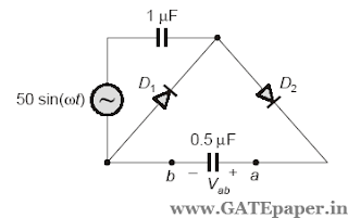
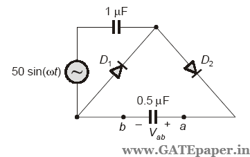
14. In the circuit shown, assume that diodes D1 and D2 are ideal. In the steady state condition, the average voltage Vab (in volts) across 0.5 µF capacitor is ____________
Solution : https://www.youtube.com/watch?v=2ZfO7mplk4g
1. For the circuit in figure, the instantaneous current i1(t) is
2007
2. In the AC network shown in the figure, the phasor voltage VAB(in volts) is:
2008
Common Data Questions: 3 & 4
The following series RLC circuit with zero initial conditions is excited by a unit impulse function δ(t).
3. For t > 0, the output voltage Vc(t) is
4. For t > 0, the voltage across the resistor is
2009
5. The time domain behaviour of an RL circuit is represented as shown below. For an initial current of i(0) = Vo/R, the steady state value of the current is given by
2010
6. The current I in the circuit shown is
a) - j1 A
b) j1 A
c) 0 A
d) 20 A
2011
7. In the circuit shown below, the Norton equivalent current in amperes with respect to the terminals P and Q is
a) 6.4 - j 4.8
b) 6.56 - j 7.87
c) 10 + j 0
d) 16 + j 0
8. The circuit shown below is driven by a sinusoidal input Vi = Vpcos(t/RC). The steady state output Vo is
9. In the circuit shown below, the current I is equal to
2012
10. In the circuit shown below, the current through the inductor is
2014
11. In the circuit shown in the figure, the value of node voltage V2 (in volts) is
a) 22 + j 2
b) 2 + j 22
c) 22 – j 2
d) 2 – j 22
12. The steady state output of the circuit shown in the figure is given by y(t) = A(ω) sin(ωt + φ(ω)).
If the amplitude |A(ω)| = 0.25, then the frequency ω is
13. In the circuit shown in the figure,
the value of Vo(t) (in volts) for t → ∞ is ___________
2015
14. In the circuit shown, assume that diodes D1 and D2 are ideal. In the steady state condition, the average voltage Vab (in volts) across 0.5 µF capacitor is ____________
Thankyou..
ReplyDeleteThis comment has been removed by the author.
ReplyDelete